What is React Flow Edge Overlapping Circuit?
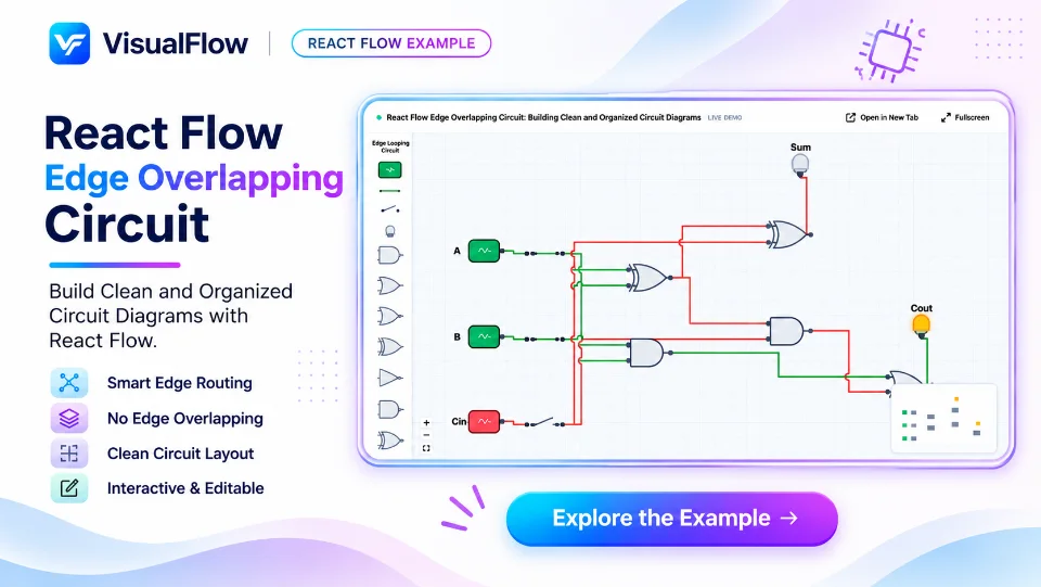
React Flow Edge Overlapping Circuit is an interactive circuit visualization example that demonstrates how to build complex digital logic diagrams using custom nodes, connectors, and overlapping edges. Designed with React Flow, this example recreates a digital full-adder circuit where multiple signal paths connect logic gates while navigating through intersecting and overlapping connections.
The circuit features essential digital logic components, including AND, OR, and XOR gates, input switches, and output indicators. Its structured grid-based canvas makes it easier to understand how signals travel between components, even when multiple edges share or cross similar paths.
Whether you're building digital circuit simulators, workflow editors, electronic design tools, or technical diagramming applications, this example demonstrates how React Flow can handle complex node connections with a clean and organized visual experience.
Key Features of React Flow Edge Overlapping Circuit
1. Custom Logic Gate Nodes
Create reusable logic gate components using React Flow custom nodes. The circuit includes AND, OR, XOR, and other gate symbols, each with clearly defined input and output handles.
These custom nodes make it possible to build interactive circuit diagrams that closely resemble traditional digital electronics schematics.
2. Edge Overlapping and Connection Management
The example demonstrates how multiple connections can travel through nearby paths and intersect across the canvas. Carefully managed edge routing helps maintain circuit readability while handling complex connections between logic gates.
This approach is particularly useful when building large node-based diagrams with multiple interconnected components.
The circuit includes interactive input switches labeled A, B, and Cin (Carry Input). Users can change input states to simulate different binary combinations and observe how signals propagate through the connected logic gates.
4. Dynamic Signal Visualization
Different wire colors represent signal states, making it easier to distinguish active and inactive connections. As the circuit inputs change, the connected paths and output indicators can respond dynamically.
This visual feedback makes complex circuit behavior easier to understand.
5. Grid-Based Circuit Canvas
A structured grid background provides alignment and positioning references for logic gates and connecting edges. Combined with zooming and panning controls, the canvas offers a convenient environment for exploring detailed circuit layouts.
Understanding the Full Adder Circuit
The diagram represents a full-adder circuit, a fundamental digital electronics component that adds three binary inputs: A, B, and Cin.
It produces two outputs:
- Sum: The binary addition result.
- Cout: The carry output generated from the addition.
The full-adder logic follows these Boolean expressions:
Sum = A ⊕ B ⊕ Cin
Cout = (A · B) + (Cin · (A ⊕ B))
The circuit combines XOR, AND, and OR logic gates to calculate both outputs.
Use Cases
React Flow Edge Overlapping Circuit can serve as a foundation for several applications:
- Digital logic circuit simulators.
- Interactive electronics learning platforms.
- Boolean expression visualizers.
- Node-based engineering applications.
- Electronic circuit diagram editors.
- Complex workflow and data-flow visualization tools.
Build Complex Circuit Diagrams with React Flow
React Flow provides the flexibility to create custom node-based interfaces with interactive connections, reusable components, and customizable edge rendering. By combining custom logic gate nodes with carefully designed edge routing, developers can build sophisticated circuit diagrams directly in the browser.
The Edge Overlapping Circuit example demonstrates how these capabilities can be used to represent real digital logic systems while maintaining a structured and interactive canvas.
Whether you are developing an educational electronics tool or a professional diagramming application, this example offers a practical starting point for building advanced circuit visualization experiences.
 VisualFlow