React Flow Edge Overlapping Circuit: Building Clean and Organized Circuit Diagrams
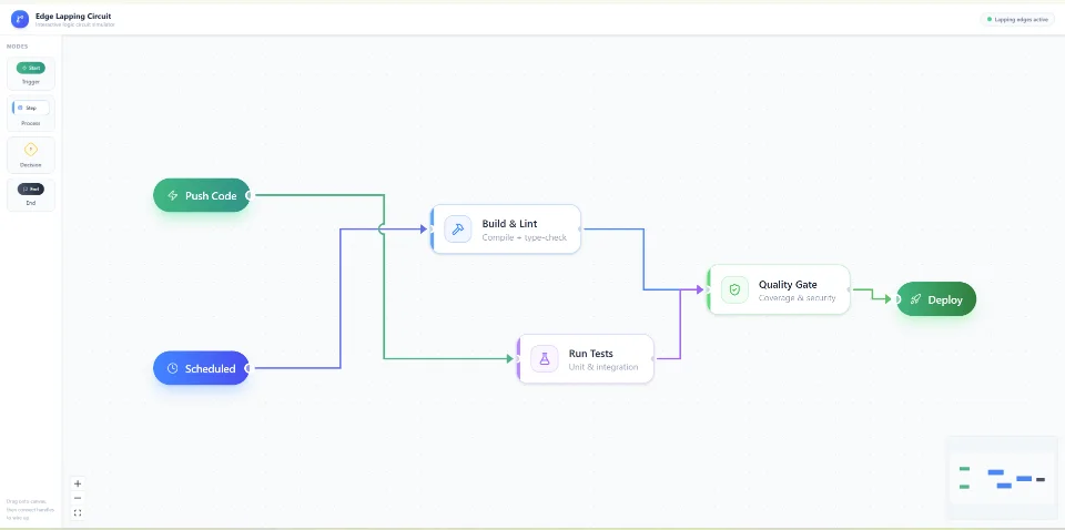
The React Flow Edge Overlapping Circuit demonstrates how multiple nodes and connecting edges can be organized to represent a digital logic circuit while maintaining a clear and understandable visual structure.
alt textThe React Flow Edge Overlapping Circuit demonstrates how multiple nodes and connecting edges can be organized to represent a digital logic circuit while maintaining a clear and understandable visual structure.
What Is Edge Overlapping in React Flow?
Edge overlapping occurs when multiple connections share the same visual space or intersect with other edges while connecting different nodes in a React Flow canvas.
In simple node-based applications, a few connections may not create any significant visual problems. However, in more complex diagrams, overlapping edges can make it difficult to identify which node is connected to another.
Common challenges include:
Multiple edges passing through the same area.
Connection lines crossing between different nodes.
Unorganized connections in circuit and logic gate visualizations.
These problems become more noticeable when developing advanced workflow editors, automation platforms, circuit designers, and interactive diagramming tools.
Understanding the React Flow Circuit Diagram
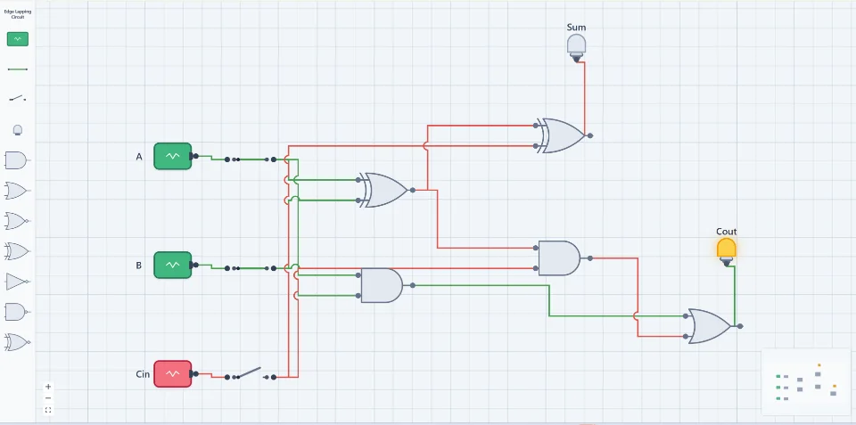
This example demonstrates a digital logic circuit using React Flow. The diagram contains three input signals (A, B, and Cin), multiple logic gates, and two output indicators (Sum and Cout).
The circuit follows a full-adder-style structure, where input signals travel through different logic gates to produce the final outputs.
The visualization includes:
1. Input Nodes
The circuit starts with three input nodes: A, B, and Cin. These nodes represent the input signals that travel through the circuit.
2. Logic Gate Nodes
Different logic gates process the incoming signals. The diagram uses XOR, AND, and OR gate structures to represent the logical operations.
3. Connected Edges
Edges represent the flow of signals between the input nodes, logic gates, and output nodes. Multiple connections are routed across the canvas, making edge organization especially important.
4. Output Nodes
The circuit produces two outputs: Sum and Cout. These output indicators represent the final results of the logical operations.
How to Manage Edge Overlapping in React Flow
React Flow provides a flexible edge system that allows developers to customize how connections are displayed. However, creating clean connections in a complex diagram often requires additional routing and positioning strategies.
Here are some useful approaches:
1. Use Custom Edge Components
React Flow supports custom edge components, allowing developers to control the appearance and routing of connections.
You can use custom SVG paths to create more predictable edge routes instead of relying entirely on default connection behavior.
2. Implement Orthogonal Edge Routing
Orthogonal routing is particularly useful for circuit diagrams and technical workflows.
Instead of drawing diagonal connections, edges follow horizontal and vertical paths. This creates a structured appearance and makes complex connections easier to follow.
3. Apply ELK.js for Automatic Layout
ELK.js (Eclipse Layout Kernel) is a powerful layout engine for organizing complex node-based diagrams.
When combined with React Flow, ELK.js can help position nodes and calculate connection layouts based on graph relationships.
It is especially useful for:
Complex workflow diagrams.
Nested node structures.
Digital circuit visualization.
Large dependency graphs.
Multi-directional node connections.
4. Add Edge Offset and Routing Points
When multiple edges connect to nearby nodes, introducing intermediate routing points can help separate their paths.
Custom edge routing can create different paths for connections that would otherwise overlap.
5. Use Visual Indicators for Signal Flow
Color-coded edges can improve the readability of circuit diagrams. For example, different colors can represent active signals, inactive signals, or different connection states.
This makes it easier to understand how information travels through a complex graph.
Why Edge Management Matters in Workflow Builders
Edge management is not only important for digital circuit diagrams. It is also essential for modern workflow builders and visual programming applications.
Applications such as automation platforms, process designers, and AI workflow editors often contain many interconnected nodes.
Without proper edge routing, users may struggle to understand the relationships between different workflow steps.
A well-designed React Flow canvas should provide:
Clear connection paths.
Minimal unnecessary edge intersections.
Consistent spacing between nodes.
Readable connection handles.
Responsive zooming and panning.
Organized layouts for large diagrams.
These improvements create a better user experience and make complex visual workflows easier to maintain.
Build Better Node-Based Applications with VisualFlow
VisualFlow explores practical implementations of React Flow and modern node-based interfaces. From custom edges and nested flows to complex circuit diagrams and workflow automation, VisualFlow demonstrates how developers can build more interactive and organized visual applications.
The React Flow Edge Overlapping Circuit example highlights how multiple connections can be visualized in a single canvas while demonstrating the importance of edge routing, connection management, and diagram readability.
Whether you are developing a digital circuit simulator, workflow builder, automation editor, or visual programming tool, managing overlapping edges is an important part of creating a professional node-based interface.
How it works
Source code
Get the Complete Source Code
Explore the implementation, customize the components, and use the example as a foundation for your next project.
Edge overlapping is a common challenge when building workflow editors, node-based applications, and interactive diagrams with React Flow. As workflows become more complex, multiple edges may cross, overlap, or follow similar paths, making the diagram difficult to read and understand.
React Flow Edge Overlapping Circuit is an interactive circuit visualization example that demonstrates how to build complex digital logic diagrams using custom nodes, connectors, and overlapping edges. Designed with React Flow, this example recreates a digital full-adder circuit where multiple signal paths connect logic gates while navigating through intersecting and overlapping connections.
 VisualFlow